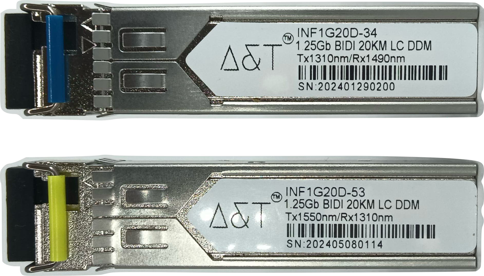
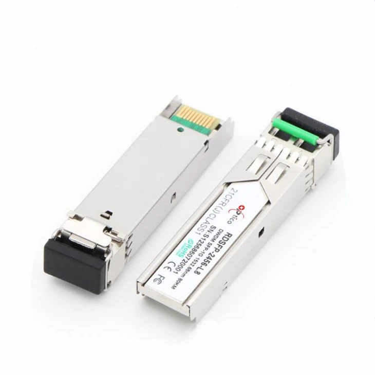
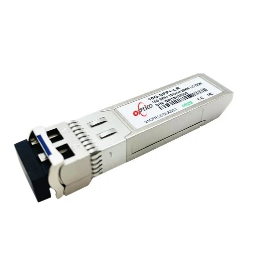
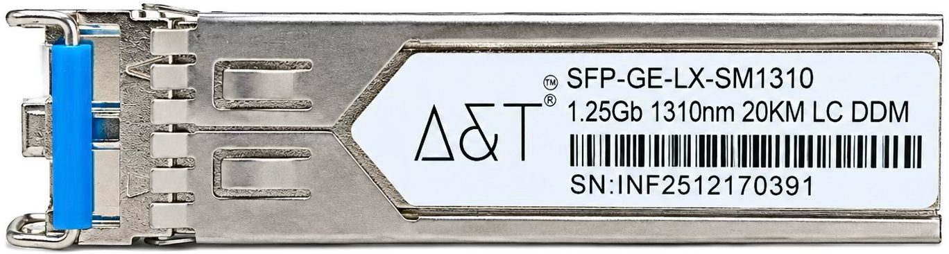
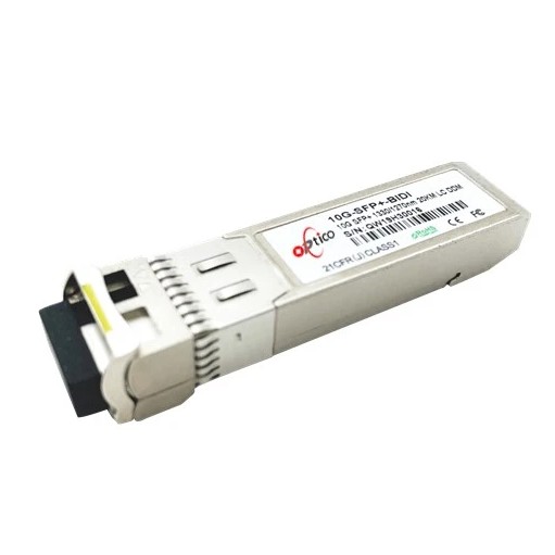
- Up to 1.25Gb/s data links
- Single LC connector
- Hot-pluggable SFP footprint
- 1310nm FP laser transmitter
- 1490nm InGaAs PIN receiver
- RoHS compliant and Lead Free
- Up to 20km on 9/125um SMF
- Metal enclosure for lower EMI
- Single +3.3V power supply
- Low power dissipation <800mW
- Commercial and industrial operating temperature optional
- SFP MSA SFF-8074i Compliant
Applications:
- Gigabit Ethernet
- 1x Fibre Channel
Product Selection:
|
Part Number
|
Operating temperature
|
DDMI
|
|
BIDI SFP 1.25G TX1310/RX1550 20KM
|
Commercial
|
No
|
|
BIDI SFP 1.25G TX1310/RX1550 20KM
|
Commercial
|
Yes
|
|
BIDI SFP 1.25G TX1310/RX1550 20KM
|
Industrial
|
No
|
|
BIDI SFP 1.25G TX1310/RX1550 20KM
|
Industrial
|
Yes
|
Product Selection:
- ESD to the Electrical PINs: compatible with MIL-STD-883 Method 3015
- ESD to the LC Receptacle: compatible with IEC 61000-4-2
- Immunity compatible with IEC 61000-4-3
- EMI compatible with FCC Part 15 Class B EN55022 Class B (CISPR 22B) VCCI Class B
- Laser Eye Safety compatible with FDA 21CFR 1040.10 and 1040.11 EN60950, EN (IEC) 60825-1,2
- RoHs compliant with 2002/95/EC 4.1&4.2 2005/747/EC
Pin Descriptions:
|
Pin
|
Symbol
|
Name/Description
|
Ref
|
|
1
|
VeeT
|
Transmitter Ground (Common with Receiver Ground)
|
1
|
|
2
|
TX Fault
|
Transmitter Fault.
|
|
|
3
|
TX Disable
|
Transmitter Disable. Laser output disabled on high or open.
|
2
|
|
4
|
MOD_DEF(2)
|
Module Definition 2. Data line for Serial ID.
|
3
|
|
5
|
MOD_DEF(1)
|
Module Definition 1. Clock line for Serial ID.
|
3
|
|
6
|
MOD_DEF(0)
|
Module Definition 0. Grounded within the module.
|
3
|
|
7
|
Rate Select
|
No connection required
|
|
|
8
|
LOS
|
Loss of Signal indication. Logic 0 indicates normal operation.
|
4
|
|
9
|
VeeR
|
Receiver Ground (Common with Transmitter Ground)
|
1
|
|
10
|
VeeR
|
Receiver Ground (Common with Transmitter Ground)
|
1
|
|
11
|
VeeR
|
Receiver Ground (Common with Transmitter Ground)
|
1
|
|
12
|
RD-
|
Receiver Inverted DATA out. AC Coupled
|
|
|
13
|
RD+
|
Receiver Non-inverted DATA out. AC Coupled
|
|
|
14
|
VeeR
|
Receiver Ground (Common with Transmitter Ground)
|
1
|
|
15
|
VccR
|
Receiver Power Supply
|
|
|
16
|
VccT
|
Transmitter Power Supply
|
|
|
17
|
VeeT
|
Transmitter Ground (Common with Receiver Ground)
|
1
|
|
18
|
TD+
|
Transmitter Non-Inverted DATA in. AC Coupled.
|
|
|
19
|
TD-
|
Transmitter Inverted DATA in. AC Coupled.
|
|
|
20
|
VeeT
|
Transmitter Ground (Common with Receiver Ground)
|
1
|
Note:
- Circuit ground is internally isolated from chassis ground.
- Laser output disabled on TX Disable >2.0V or open, enabled on TX Disable<0.8V.
- Should be pulled up with 4.7k - 10kohms on host board to a voltage between 2.0V and 3.6V. MOD_DEF(0) pulls line low to indicate module is plugged in.
- LOS is open collector output. Should be pulled up with 4.7k – 10kohms on host board to a voltage between 2.0V and 3.6V. Logic 0 indicates normal operation; logic 1 indicates loss of signal.
Recommend Circuit Schematic:
Absolute Maximum Ratings:
|
Parameter
|
Symbol
|
Min
|
Type
|
Max
|
Unit
|
Ref
|
|
Maximum Supply Voltage
|
Vcc
|
-0.5
|
-
|
+4.0
|
V
|
|
|
Storage Temperature
|
TS
|
-40
|
-
|
+85
|
°C
|
|
|
Operating Humidity
|
RH
|
5
|
-
|
95
|
%
|
|
Recommended Operating Conditions:
|
Parameter
|
Symbol
|
Min
|
Typ
|
Max
|
Unit
|
Ref
|
|
Power Supply Voltage
|
Vcc
|
3.13
|
3.30
|
3.47
|
V
|
|
|
Power Supply Current
|
Icc
|
-
|
-
|
250
|
mA
|
|
|
Case Operating Temperature
|
Tc
|
0
|
-
|
+70
|
°C
|
1
|
|
TI
|
-40
|
-
|
+85
|
2
|
|
Data Rate(Gigabit Ethernet)
|
-
|
-
|
1.25
|
-
|
Gbps
|
|
|
9/125um G.652 SMF
|
Lmax
|
-
|
-
|
20
|
km
|
|
Note:
- For commercial class product.
- For industrial class product.
Electrical Characteristics (TOP=25°C, Vcc=3.3Volts)
|
Parameter
|
Symbol
|
Min
|
Typ
|
Max
|
Unit
|
Ref.
|
|
Transmitter
|
|
Input differential impedance
|
Rin
|
-
|
100
|
-
|
Ω
|
1
|
|
Single ended data input swing
|
Vin, pp
|
250
|
-
|
1200
|
mV
|
|
|
TX Disable-High
|
-
|
Vcc – 1.3
|
-
|
Vcc
|
V
|
|
|
TX Disable-Low
|
-
|
Vee
|
-
|
Vee+ 0.8
|
V
|
|
|
TX Fault-High
|
-
|
Vcc-0.5
|
-
|
Vcc
|
V
|
|
|
TX Fault-Low
|
-
|
Vee
|
-
|
Vee+0.5
|
V
|
|
|
Receiver
|
|
Single ended data output swing
|
Vout, pp
|
300
|
400
|
800
|
mV
|
2
|
|
Data output rise time
|
tr
|
-
|
-
|
175
|
ps
|
3
|
|
Data output fall time
|
tf
|
-
|
-
|
175
|
ps
|
3
|
|
LOS-High
|
-
|
Vcc – 0.5
|
|
Vcc
|
V
|
|
|
LOS-Low
|
-
|
Vee
|
|
Vee+0.5
|
V
|
|
Note:
- AC coupled.
- Into 100 ohm differential termination.
- 20 – 80 %
Optical Characteristics (TOP=25°C, Vcc=3.3 Volts)
|
Parameter
|
Symbol
|
Min
|
Typ
|
Max
|
Unit
|
Ref.
|
|
Transmitter
|
|
Output Opt. Power
|
PO
|
-9
|
-
|
-3
|
dBm
|
1
|
|
Optical Wavelength
|
λ
|
1275
|
1310
|
1350
|
nm
|
|
|
Spectral Width
|
σ
|
-
|
-
|
3
|
nm
|
|
|
Optical Rise/Fall Time
|
tr/tf
|
-
|
-
|
260
|
ps
|
2
|
|
Total Jitter
|
TJ
|
-
|
-
|
200
|
ps
|
|
|
Optical Extinction Ratio
|
ER
|
9
|
-
|
-
|
dB
|
|
|
Receiver
|
|
RX Sensitivity @1.25 Gb/s
|
RSENS
|
-
|
-
|
-25
|
dBm
|
3, 4
|
|
Maximum Received Power
|
RXMAX
|
-2
|
-
|
-
|
dBm
|
|
|
Optical Center Wavelength
|
λC
|
1470
|
1490
|
1510
|
nm
|
|
|
LOS De-Assert
|
LOSD
|
-
|
-
|
-26
|
dBm
|
|
|
LOS Assert
|
LOSA
|
-40
|
-
|
-
|
dBm
|
|
|
LOS Hysteresis
|
-
|
0.5
|
-
|
5
|
dB
|
|
Note:
- Class 1 Laser Safety.
- Unfiltered, 20-80%. Complies with Gigabit Ethernet eye masks when filtered.
- Measured with conformance signals defined in FC-PI-2 Rev. 10.0 specifications.
- Measured with PRBS 2 -1 at 10 BER
Mechanical Specifications:
SFP Small Form Factor Pluggable (SFP) transceivers are compatible with the dimensions defined by the SFP Multi-Sourcing Agreement (MSA). EEPROM Information:
EEPROM memory map specific data field description is as below:
Digital Diagnostic Monitoring Interface:
Five transceiver parameter values are monitored. The following table defines the monitored parameter’s accuracy.
|
Parameter
|
Range
|
Accuracy
|
Calibration
|
|
Temperature
|
0 to +70°C (C)
|
±3°C
|
Internal
|
|
-40 to +85°C (I)
|
|
Voltage
|
2.97 to 3.63V
|
±3%
|
Internal
|
|
Bias Current
|
0 to 100mA
|
±10%
|
Internal
|
|
TX Power
|
-9 to -3dBm
|
±3dB
|
Internal
|
|
RX Power
|
-25 to -2dBm
|
±3dB
|
Internal
|
.
.