The Site is under maintenance
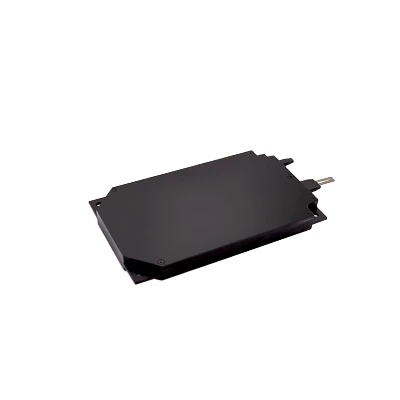
Arrayed Waveguide Grating

Arrayed Waveguide Grating-AWG DWDM

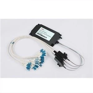
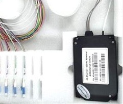
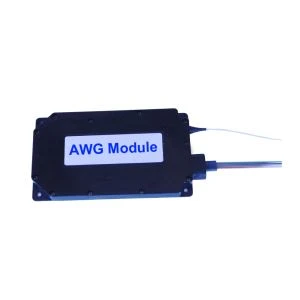
Array waveguide grating is based on basic optical principle of different wavelengths linear interference between each other. This means that, if every channel use the wavelength nuances with the light, the light of the many channels can be carried by a single optical fiber, and there is only negligible signal crosstalk.The array waveguide grating, in the transmission end, can compound the lights of multiple channels into a single optical fiber, and at the same time, separate the lights again at the receiving end.
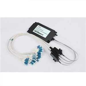
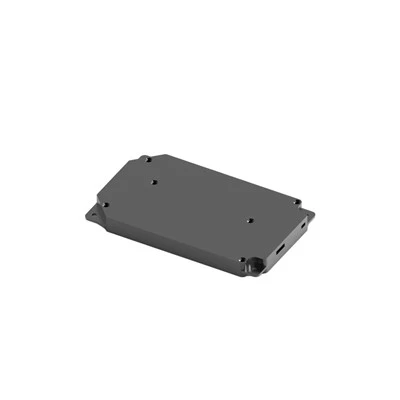
Belief Introduction of Arrayed Waveguide Grating-AWG DWDM:

Array waveguide grating is based on basic optical principle of different wavelengths linear interference between each other. This means that, if every channel use the wavelength nuances with the light, the light of the many channels can be carried by a single optical fiber, and there is only negligible signal crosstalk.The array waveguide grating, in the transmission end, can compound the lights of multiple channels into a single optical fiber, and at the same time, separate the lights again at the receiving end.
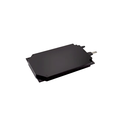
Parameters

Condition

Specs

Units


Min

Typ

Max


Number of Channels


40


Number Channel Spacing

100GHz

100

GHz


Cha. Center Wavelength

ITU frequency.

C -band

nm


Clear Channel Passband


±0.1

nm


Wavelength Stability

Maximum range of the wavelength error  of all channels and temperatures in average polarization.

±0.05

nm


-1 dB Channel Bandwidth

Clear channel bandwidth defined by passband shape. For each channel

0.4


nm

-3 dB Channel Bandwidth

Clear channel bandwidth defined by passband shape. For each channel

0.6


nm

Optical Insertion Loss at ITU grid

Defined as the minimum transmission at ITU wavelength for all channels. For each channel, at all temperatures and polarizations.


4.5

6.0

dB

Adjacent Channel Isolation

Insertion loss difference from the mean transmission at the ITU grid wavelength to the highest power, all polarizations, within the ITU band of the adjacent channels.

25


dB

Non-Adjacent, Channel

Isolation

Insertion loss difference from the mean transmission at the ITU grid wavelength to the highest power, all polarizations, within the ITU band of the nonadjacent channels.

30


dB

Total Channel Isolation

Total cumulative insertion loss difference from the mean transmission at the ITU grid wavelength to the highest power, all polarizations, within the ITU band of all other channels, including adjacent channels.

22


dB

Insertion Loss Uniformity

Maximum range of the insertion loss variation within ITU across all channels, polarizations and temperatures.


1.0

1.5

dB

Directivity(Mux Only)

Ratio of reflected power out of any channel(other than channel n)to power in from the input channel n

40


dB

Insertion Loss Ripple

Any maxima and any minima of optical loss across ITU band, excluding boundary points, for each channel at each port


0.5

dB

Optical Return loss

Input & output ports

40


dB

PDL/Polarization Dependent Loss in Clear

Channel Band

Worst-case value measured in ITU band


0.3

0.5

dB

Polarization Mode

Dispersion


0.5

ps

Maximum Optical Power


23

dBm

MUX/DEMUX input/ output

Monitoring range


-35


+23

dBm

Related Product

100G 20CH DWDM AAWG Gaussian Type

100G 20CH DWDM AAWG Gaussian Type

View Category
Mini 48CH Athermal AWG Module

Mini 48CH Athermal AWG Module

View Category
75G 64CH Flat Top AAWG

75G 64CH Flat Top AAWG

View Category
100G Flat-top 48CH AWG

100G Flat-top 48CH AWG

View Category
100G 40CH Demux AAWG NC

100G 40CH Demux AAWG NC

View Category
4CH CWDM AWG

4CH CWDM AWG

View Category
Arrayed Waveguide Grating-AWG DWDM

Arrayed Waveguide Grating-AWG DWDM

View Category
AWG Arrayed Wave-guide Grating

AWG Arrayed Wave-guide Grating

View Category
50G 96CH AAWG Module

50G 96CH AAWG Module

View Category

Select Your States for Arrayed Waveguide Grating-AWG DWDM